Sunday, September 30, 2018

Installing ROS 2 (Melodic) in Windows 10


Introduction:

Requirements:


Objectives:


Methodology:


Summary:


Remarks:


Conclusion:


Tuesday, August 28, 2018

Neato Lidar XV11 + ROS


Introduction:

Hello once again, we are quite a bit focus on finishing  tutorials about  lidars. These  kinds of sensors are  important because SLAM in R.O.S rely much about the use of it. As much as possible we are trying to choose, reverse engineer , economize the build of  our rotating laser sensors. Our  purpose is to craft and replicate  lidars into a more affordable and efficient distant ranging sensors. Otherwise, though robotic is interesting, not everybody will be doing industrial robots  because of cost and that is not practical for a mass patronage.

For a few days we had already tackle introduction and hands on tutorial as motivational guide for a hobbyists to start using R.O.S. After familiarizing the usefulness , we will proceed to interfacing encoders and motors to relate the actuation ,speed,revolution of motors when running,this time all are test and first. Next step is to put wheels on the chassis and see for our selves how our code able to simulate movement of the robots from the visualized GUI to what we are able to observe it in a real world action.

One of the cheapest and known lidar was the Neato XV11 lidar, this was because a vacuum cleaner robot was deployed world wide so old machine produce stocks of 2nd hand lidars. We choose this surplus or second hand lidar because of course it is cheaper and its hacks had complete documentations on the internet , so not a bad choice for us Filipino.

I have just bought Neato XV11 lidar recently and saw a lot of tutorials on the internet and am glad about it. One I have observed was that it needs to power source 5V and 3.3V other hobbyist tried to isolate the source so they needed two modules (DC-DC step down and USB-to Serial), but its obvious that USB-t Serial module has 5V/3.3V so it is perfect for the Lidar power requirements.The rest are instruction to be discussed below. Hope we can get more units as stocks online :)


Requirements:
Neato XVII Lidar
ROS Kinetic
Ubuntu 16.04
USB to Serial module with 5V and 3.3V

Objectives:


Methodology:


Image result for Neato Lidar


Summary:
Trouble:
Shooting:


Conclusions:

It is ideal cost effective LIDAR for hobbyist.

Sunday, August 26, 2018

LaserScan ROS + Arduino


Introductions:
Yes, a happy weekend plus a holiday on Monday, so with  choco and cookies placed on the table ah what  a little  time to spare   ticking keyboards here. Anyway, we will be continuing our R.O.S tutorials , and its all about understanding how LIDARs works in R.O.S. We knew that the scattered lines served as the perception of a robot using this kind of sensors. These lines forming figures creates a dimensions of area used to be navigated by robots.The rays of line were formed as a collection of distances measured or sensed by LIDAR/LEDDAR).Thus infra red lights emitted by transmitter are then feedback to the receiver usually the photo diode. An array of these measured distances  will be included  in the parameters' value of   scanning angle,time,and the number of points how wide is the coverage of scanning.All these parameters are wrapped in the "Sensor Messages/LaserScan" in a R.O.S string packet format.

This time, the deal is using rosserial library, "ros_lib  and ROS Sensors Messages:: LaserScan. The Arduino DUE will  process the  publishing of  "LaserScan" messages and its topic. Using "ros_lib" an Arduino Due  communicate  with the host R.O.S installed in the computer (Laptop/Desktop) both of which are  connected physically via serial serial interface . In the  near future  of these tutorials, using Arduino/microcomputer will not be ideal anymore in  integrating multiple  sensors to R.O.S. This is because processing and computing will be at risk and not a practical design of  R.O.S application. In short, the use of microcontroller is only to interface sensor modules yet most  of single board computers  have IO ports to their advantage.

Thus , what we will be doing  is to get a common measuring modules such as  SAMSUNG infrared or Ultrasonic SRF04 considered as poor man's LIDAR. SG90 servo motor will carry and rotate the sensor with the speed relative to the frequency of its data acquisition. The angle of rotation is as wide as  180 degrees angle, a back and forth or  a clock and  counter clockwise directions. It is possible to rotate 360 degrees wide  but it requires a slip ring and that is an additional cost. The  interval of time,angle, and number frequency of measuring   distances can be set or adjusted depending the type of sensor or  modules being used. To accurately dump data in  R.O.S Laser scan messages , is to configure its   parameter settings, for example a 180  degrees maximum angle if   divided  by desired 90 points then the angular interval of scanning is 2 degrees.

The simple steps to code ROS Laser Scanning,first  is to initialize  Sensor messages,its laser scan function ,and  to  check topic that publish messages. The finale, use the  R.O.S visualization "rviz" to simulate the functionality of  DIY LIDAR. Okay? So let's get this done :) 

Requirements:
Software: Ubunto 16.04, ROS (kinetic)
Hardware: Arduino DUE, SBC or Laptop,SG90 Servo
                Optional : sensors (ultrasonic or infra red)

Objectives:
1)  To be able to publish a ranging(distance measurement sensor) messages from a DIY LIDAR to ROS .
2) To be able to study algorithm or program to  collect array of measurements and  feed(publish)  it into a R.O.S messages format.
3) To create a program using  rosserial library "ros_lib"  from Arduino to ROS

Methodology:
Testing Arduino Due sample code to fake laser array of data(ranges)


Arduino Due code for Laser scan


Please copy and paste the program

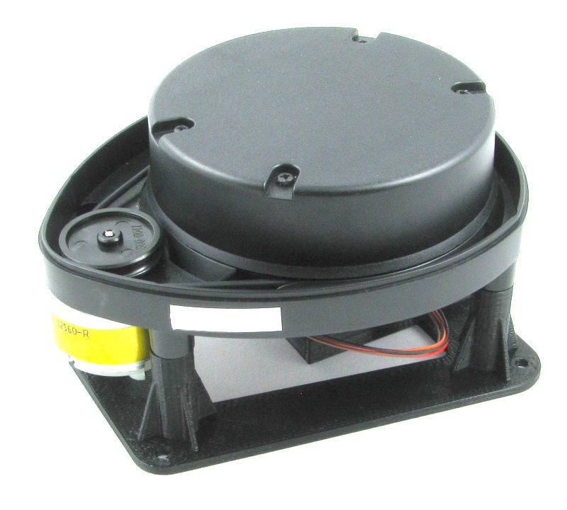
A simple setup of our DIY Lidar (photo credit to the photographer)


Open four CLI terminals:
 Run the ros core "roscore"
robook# roscore


Communicate between ROS and Arduino  using rosserial
library
robook # rosrun rosserial_python serial_node.py /dev/ttyUSB0
robook# rosrun rosserial_arduino serial_node.py _port:=/dev/ttyUSB0


Make sure that the "/laserScan" topic is being echoed or broadcasted to ROS.
robook# rostopic list
robook# rostopic echo /LaserScan
If  Arduino DUE is able to bombard those collected ranges in ROS , scrolling
stream of string may appear in the screen


Set the transformation of the frame required to accurately map the laser data
robook# rosrun tf tf_publisher_transform 0.0 0.0 0.0 0.0 0.0 0.0  /base_frame /Lidar_frame


Displaying or visualizing  the laser data, we can use RVIZ to plot
it in its grid map.
robook# rosrun rviz rviz 


By setting the ROS Visualizer "rivz": fixed frame "Lidar_frame" and LaserScan
"LaserScan". The display would eventually appear same as the screen below.


Making sure that RVIZ is properly configured , LaserScan
topic is receiving messages coming from Arduino Due,also
transformation is set properly.


Summary:
Trouble:    Arduino is not syncing to rosserial
Shooting:  Place "#define USE_USBCON" before the include "ros.h"
Trouble: No display of laser data in RVIZ
Shooting : Check if there is a laser scan topic
                 Use  #rostopic echo /LaserScan -> if this is the topic

Conclusion:
A simple code of a possible integrations of different ranging sensor to ROS


Sunday, August 5, 2018

Ultrasonic Sensor + ROS (rviz)


Introduction:
My arduino uno starter kit is saved, nobody dare to get the assignment, but we need to continue this ROS tutorials come what may.

I had been observing many questions in ros.org most of these problems are the  ROS howtos , but  it needs to understand both side of a learner and the business of a developer. Well Robotic Operating System aka ROS had proven its system dexterity . However , I would say it has along way to go to  dominate all robotics software in the market. Those are the business side of the deal because  consumers are still needing  more  robots that can  perform  dynamic services to both  households and companies tasks. Also clients are expecting that an  AI almost similar to human comprehension can be used in robots.Somehow its a gradually happening today, people and business men alike are curios and excited what these machines are capable of.

Wait a minute,as I am saying we forget some part of the pi, and these are the learners of robotics  technology they are new breed of  technicians, programmers and analysts. Or let may ask this ,who would be the sales representative of robotics company,how the marketing  competitions will be observed sooner.Whatever happens we need to realize and consider that  there will be a group of learner willing to participate the trend, but in this current scenario developers are focus on advancing development to fast tract their robotics innovations-its a point of no return. So since not all robotics knowledge is an open book yet, everybody is searching for an answers to simplify and shorten their  learning curve as much as possible.

Indeed they need tutorials with learning by doing approach , and yours truly is trying to achieve that goal ,and we are also the same-learning in progress. So please accompany as while we will treasure the technology of robotics and how ROS would simplify this intellectual craving.     (for edition


Objectives:
To use std_msg/range in ROS
To use ultrasonic SRF04 sensors and its parameters
To simulate the sensor's (frame id, topics) data inside ROS visualization tool (rviz)

Requirements:
Software:  ROS Kinetic + Ubuntu 16.04
Hardwares: Arduino Mega + Ultrasonic SRF04

Methodology:

Setup of the experiments using arduino mega 2560 and ultrasonic SRF04


Copy and paste the program


Please check the program
Test the sonar program via  serial monitor, please uncomment "Serial.println(sensoReading)

Open four terminal for each cli commands

1)Run "roscore" command


2) Run  Arduino  with  serial port argument


3)Check the topic list


4)Echo or display the data content in the "sonaRange topic"


5)Run ros visualation tool "rviz


6)In rviz GUI


7)Change frame id name from  map to  "/sonar_ranger"


8) At the bottom of the Panel Select "Add" button to add "Range" for ultrasonic
and add the publish topic "/sonaRange"


9) Select color for the prism


10) In Rviz GUI you can see the prism length varies according to the
distance emitted by the Sonar SRF04 ultrasonic sensor.
Simulate the rviz if the circular prism change is lenght as you will interrupt
the sonar range of the ultrasound.


11) Save the rviz configuration
rosrun  -d rviz  sonar_rviz  to rerun the GUI of the sonar rviz


12) Realtime simulation of Ultrasonic "SRF04 inside RVIZ


Remarks:
We summarize the use of std_msgs using range of ultrasound

Summary:
If roscore dont run in the cli please wait because it might be initiating
Or please check if the current ip address is the one being assigned in the /etc/hosts

Conclusion:
Simple experiment to use ros visualization tools